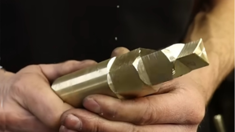
If you have ever watched a round bar become a hexagon on a lathe, you may have felt the same emotion machinists feel the first time they see it: suspicion. Lathes are supposed to make round things, right? Shafts, bushings, spacers, pins, rings, sleevesthe usual circular suspects. Then along comes polygon turning, spinning a workpiece and a cutter in synchronized motion, casually producing flats, hexes, squares, lobes, and other non-round shapes as if the machine suddenly remembered it also went to geometry class.
Polygons on a lathe refers to the machining of non-circular profilesespecially flats, squares, and hexagonswhile the part remains in the lathe. Instead of removing the workpiece and moving it to a milling machine, the machinist uses a polygon turning attachment, live tooling, C-axis control, indexing, or a milling setup on the lathe. The result can be faster cycle times, fewer setups, better concentricity, and a smaller chance that the part will develop “mysterious personality issues” after being re-clamped three times.
What Does “Polygons On A Lathe” Mean?
In basic turning, the workpiece rotates while a stationary cutting tool removes material. That motion naturally creates round surfaces. Polygon turning breaks the expectation by coordinating the rotation of the workpiece with a rotating cutter. The cutter may have multiple inserts arranged around a head, and the spindle and tool rotate at a fixed speed ratio. As each cutting edge meets the workpiece at the correct angular position, it removes material from the same repeated zones. Those repeated cuts form flat planes or lobed profiles around the part.
In practical shop language, this is often used to create wrench flats, hexagonal bolt heads, square ends, drive features, clamping surfaces, and special internal or external polygon profiles. The process is more like synchronized turning than ordinary milling, because the workpiece continues rotating while the shape is generated. That is why it looks a little like magic, although the magician is mostly math, rigidity, and a cutter head with no fear.
Why Make A Polygon On A Lathe Instead Of A Mill?
The traditional way to make flats on a round part is simple: turn the part, remove it from the lathe, clamp it in a mill, index it, cut the flats, deburr it, and hope the setup gods are smiling. This works well, but it adds handling, setup time, and alignment risk. Every time a part leaves one machine and goes to another, accuracy can suffer unless the fixturing is excellent.
Making polygons directly on the lathe can reduce those problems. The part stays in the chuck, collet, or subspindle, so the polygon feature remains closely related to the turned diameter. For production work, that can mean shorter cycle times and better repeatability. For small batches, it may eliminate an entire secondary operation. For the machinist, it may also eliminate the ancient ritual of walking across the shop carrying a half-finished part while muttering, “Please don’t make me indicate this again.”
How Polygon Turning Works
1. The Workpiece And Cutter Are Synchronized
The core idea is synchronization. The lathe spindle and the live tool spindle rotate together in a controlled ratio. For example, the cutter may rotate twice as fast as the workpiece, depending on the number of inserts and the number of flats desired. The relationship between cutter speed, spindle speed, insert count, and tool geometry determines the final polygon.
A polygon cutter does not simply mill one flat, stop, index, and mill the next. Instead, it cuts dynamically. Each insert sweeps past the rotating workpiece at the right time, carving a repeated surface. The shape emerges from the timed interaction of two rotations. It is a mechanical dance, except one partner is carbide and the other is steel, brass, or aluminum.
2. The Number Of Inserts Matters
A polygon cutter may use several cutting inserts placed evenly around a cutter head. The number of inserts affects how many flats or lobes are generated. The speed ratio between the cutter and the workpiece is just as important. A different ratio can change a hex into another polygonal profile. This is why polygon turning is usually planned around a specific tool, part diameter, and contour rather than guessed at on a Friday afternoon.
3. The Flats Are Not Perfectly Flat
Here is the small plot twist: polygon-turned flats are often very large-radius curves rather than mathematically perfect planes. To the eye and to a wrench, they may look flat enough for many applications. However, if a print demands strict flatness, conventional milling, grinding, broaching, or another finishing method may be better. Polygon turning shines when the application needs functional flats, speed, and reliable positioningnot when the inspection report is waiting with a magnifying glass and a grudge.
Common Methods For Cutting Polygons On A Lathe
Polygon Turning With Live Tooling
Modern CNC turning centers with live tooling are ideal for polygon turning. Live tooling gives the lathe a powered tool spindle capable of milling, drilling, tapping, and other secondary operations. When paired with synchronized spindle control, the live tool can create polygon features directly on the part. Machines with C-axis capability can position or coordinate the spindle angle with high precision, allowing more complex mill-turn work in one setup.
This is especially useful for production parts such as fittings, fasteners, medical components, automotive transmission parts, and shafts with wrench flats. The lathe turns the main diameters, cuts grooves or threads, then forms the polygon without releasing the workpiece. That one-setup workflow is one reason mill-turn machines have become so valuable in modern manufacturing.
C-Axis Milling And Indexing
Not every polygon on a lathe is made by true polygon turning. Sometimes a machinist uses C-axis indexing to lock or position the spindle, then mills one flat at a time with an end mill. For a hex, the spindle indexes every 60 degrees. For a square, it indexes every 90 degrees. This method is easier to understand and may produce flatter flats, but it is often slower because each surface is cut separately.
C-axis milling is a great option when the part requires accurate flatness, defined corner geometry, or features such as slots and holes positioned around the diameter. True polygon turning is usually chosen when speed and high-volume production are more important than perfect flat-plane geometry.
Manual Lathe Attachments
Polygon turning is not limited to shiny CNC machines that cost more than a house and have better climate control. Clever attachments can be used on manual lathes as well. A polygon turning attachment typically drives a cutter head in a fixed relationship to the lathe spindle. The setup requires careful alignment, safe guarding, and a good understanding of the gear or belt ratio. It is not beginner territory, but it is a fascinating solution for experienced machinists and model engineers.
Rotary Broaching And Other Alternatives
For internal hexes, squares, and special socket shapes, rotary broaching may be a better answer than polygon turning. Rotary broaching uses a slightly angled broach that wobbles as it cuts, generating internal or external polygon shapes in a lathe, mill, or screw machine. It is commonly used for socket-head screws, medical components, and small drive features. It is not the same process as polygon turning, but it belongs in the same conversation because both methods let a lathe create shapes that are not round.
Best Applications For Lathe Polygon Machining
Polygon turning is most useful when the part benefits from staying in one setup. Typical examples include hex bolt heads, wrench flats on turned fittings, square drive ends, flats for clamping, coupling features, and specialized profiles for mechanical engagement. Automotive parts may use polygon-like features for couplings or transmission components. Medical manufacturing may use advanced synchronized turning processes for special bone screws and non-round profiles. General precision shops may use it simply to avoid moving a part to a mill.
The best candidate is a part where the polygon feature is concentric with the turned diameter and where the required flatness is realistic for the process. If the feature must be dead flat, sharply cornered, and held to a tight geometric tolerance, polygon turning may still be useful as a roughing step, but it may need finishing.
Materials That Work Well
Polygon turning can be used on many machinable materials, including aluminum, brass, free-machining steels, alloy steels, and stainless steels. The exact success depends on the machine, tool geometry, insert grade, rigidity, coolant delivery, and chip control. Brass and aluminum are usually friendly. Free-machining steels can also behave nicely. Tough alloys demand more attention because interrupted cutting and synchronized engagement can punish weak setups.
Chip control matters because polygon turning is not a gentle spa treatment for metal. The cutter repeatedly engages and exits the material, so chips must clear cleanly. Built-up edge, poor coolant flow, or a flexible holder can create chatter, rough surfaces, and inaccurate flats. A rigid toolholder, sharp inserts, proper speed, and stable workholding are not optional; they are the price of admission.
Setup Tips For Better Polygon Turning
Start With A Rigid Setup
Rigidity is everything. Keep tool overhang short, use the correct holder, confirm the cutter head is properly seated, and make sure the workpiece is securely held. If the workpiece sticks too far out of the chuck or collet, the cut may chatter. Chatter is the machine’s way of saying, “I warned you, but you thought hope was a setup strategy.”
Check Synchronization Carefully
The spindle-to-tool speed ratio controls the geometry. On CNC machines, this means using the correct program, machine option, and synchronization command. On mechanical attachments, it means verifying the belt, gear, or drive relationship before cutting. A small mistake in ratio can produce the wrong number of flats or a shape that looks like it escaped from a geometry textbook during a thunderstorm.
Understand The Tolerance Requirement
Before choosing polygon turning, read the print carefully. Is the flat only for a wrench? Is it a cosmetic feature? Does it need to locate another component? Does it have a true position, profile, or flatness callout? The process choice should follow the tolerance, not the other way around. Polygon turning is fast and elegant, but it is not a universal replacement for milling.
Use The Right Cutting Data
Feeds and speeds depend on material, insert grade, cutter diameter, tool count, and machine power. Because polygon turning involves synchronized interrupted cutting, conservative first cuts are wise. After verifying the geometry, surface finish, and chip formation, the process can be optimized. In production, even a few seconds saved per part can matter, but only after the process is stable. A fast crash is still a crash; it just arrives with enthusiasm.
Safety Considerations
Any lathe operation deserves respect, and polygon turning adds rotating live tooling to the usual rotating workpiece hazards. Guards should be in place, the chuck key should be removed immediately, tools should be secured, and the setup should be checked before spindle start. Operators should never reach into the machine while anything is rotating. Rotating parts, flying chips, and pinch points are not theoretical risks; they are the reason safety manuals sound like they were written by someone who has seen things.
On CNC equipment, dry runs, graphics simulation, reduced rapid override, and single-block testing are useful habits. Confirm clearances around the chuck, turret, live toolholder, subspindle, tailstock, and part catcher. Polygon tools can be larger than standard turning tools, so clearance deserves extra attention. On manual or custom attachments, guarding becomes even more important because exposed rotating mechanisms can create entanglement hazards.
Advantages Of Making Polygons On A Lathe
The biggest advantage is efficiency. A shop can combine turning and polygon machining in one setup, reducing handling and improving throughput. Accuracy can also improve because the polygon feature is machined relative to the turned surfaces without re-clamping. For parts that need wrench flats or drive features, the process can be extremely productive.
Another advantage is floor-space efficiency. A mill-turn lathe with live tooling can perform operations that once required multiple machines. That does not make mills obsolete, of course. It simply means the lathe has learned a few new tricks and now wants a raise.
Limitations And Common Mistakes
The main limitation is geometry. Polygon-turned flats may have slight curvature. Corners may not match what a milling process would produce. Tooling may be specialized and expensive. Programming or synchronization errors can scrap parts quickly. Also, not every lathe has the horsepower, live tooling, C-axis control, or software option required for the job.
Common mistakes include using too much overhang, ignoring flatness requirements, selecting the wrong insert count or speed ratio, failing to verify clearances, and treating polygon turning like ordinary milling. It is not ordinary milling. It is a synchronized process that rewards planning and punishes guessing.
Real-World Experience: What It Feels Like To Cut Polygons On A Lathe
The first time you set up polygons on a lathe, the process can feel backward. You are standing in front of a machine famous for making round parts, and now you are asking it to make a hex. The machine does not care, because machines are emotionally unavailable, but the operator usually does. There is a moment before cycle start when you double-check the program, the tool number, the spindle direction, the live tool speed, the clearance, the coolant, the door, and possibly your life choices.
A good first experience usually starts with soft material. Aluminum is friendly because it cuts cleanly and forgives a little nervousness. Brass is also pleasant, though it requires correct tool geometry and attention to chip behavior. Steel feels more serious. When the cutter first engages, the sound is different from regular turning. It has a rhythmic quality because the cutting edges meet the workpiece in repeated intervals. If the setup is rigid and the synchronization is correct, the shape appears surprisingly quickly. One minute there is a round bar; the next minute there are flats. It is the kind of shop moment that makes people stop pretending they were not watching.
The most useful lesson is that inspection tells the truth. A polygon may look excellent at the machine, especially with coolant still shining on it. Then the micrometer, optical comparator, CMM, or flatness check gives the real report. For wrench flats, the result may be perfect for purpose. For a precision mating feature, it may reveal that the “flat” is actually a very gentle curve. That does not mean the process failed. It means the process has a personality, and the drawing must be compatible with that personality.
Another lesson is that workholding matters more than optimism. A part held too far out of a collet may chatter. A weak live toolholder may leave witness marks. A dull insert may push instead of cut. When the setup is correctedshorter stickout, sharper insert, better coolant, improved speed ratiothe same machine can suddenly behave like a professional. Machining often looks mysterious until you remove the loose, dull, flexible, poorly supported parts of the mystery.
In small shops, the decision often comes down to time. If you only need one part, milling flats after turning may be faster than designing a polygon setup. If you need hundreds or thousands, polygon turning becomes very attractive. Saving even ten or twenty seconds per part can become hours over a run. More importantly, one-setup machining reduces the chance of human variation. The part does not get removed, flipped, indicated, re-clamped, and re-explained to the universe.
The best shop advice is to start simple. Try a basic hex on scrap stock. Record the spindle speed, live tool speed, insert count, material, feed, and measured results. Adjust one variable at a time. Keep notes like a machinist, not like a detective in the final scene of a movie. Once the process is stable, move to the actual part. Polygon turning is not hard once understood, but it is not a place for heroic improvisation. The machine will do exactly what the setup tells it to do, including the embarrassing parts.
Conclusion
Polygons on a lathe prove that turning is not limited to round geometry. With live tooling, C-axis control, polygon cutters, synchronized spindles, or specialized attachments, a lathe can produce hexes, flats, squares, lobes, and custom profiles without moving the part to another machine. The process is fast, efficient, and extremely useful when the polygon feature relates directly to a turned diameter.
Still, polygon turning is not magic and not always the best choice. The flats may be slightly curved, tooling must be selected carefully, synchronization must be correct, and safety must be treated seriously. For wrench flats, bolt heads, clamping surfaces, and production parts, it can be a beautiful solution. For strict flatness or sharp-corner requirements, milling or finishing may still win. The smart machinist does not ask, “Can the lathe make a polygon?” The smart machinist asks, “Can this process make the polygon this drawing actually needs?” That question saves time, tools, parts, and occasionally pride.