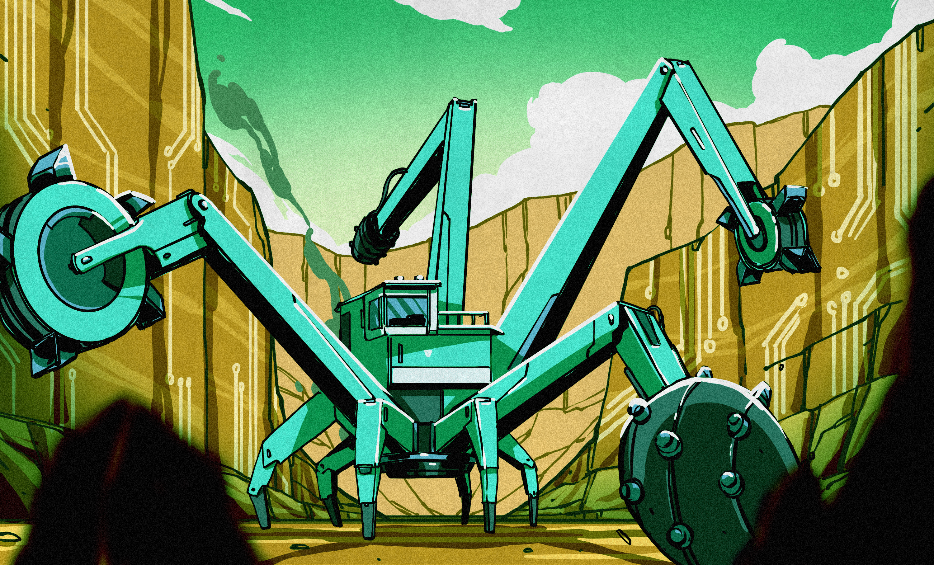
A homemade printed circuit board used to mean a small chemistry experiment: copper-clad board, resist, an etchant, a plastic tray, and at least one shirt that would never be the same again. Chemical etching ght situation. But desktop CNC PCB milling has made many makers ask a fair question: why dissolve copper when a machine can simply cut away what you do not need?
PCB milling, also called isolation milling or isolation routing, uses a CNC machine and small cutting tools to carve narrow channels around traces, drill holes, and cut the board outline. Instead of removing all exposed copper with chemicals, the machine removes only enough copper to electrically isolate each connection. It is fast, tidy in some ways, delightfully direct, and a little unforgiving when your design thinks a 0.3 mm trace gap is a reasonable lifestyle choice.
This guide compares PCB etching and PCB milling in practical terms: speed, cost, safety, design flexibility, limitations, workflow, and the kinds of projects that make one method smarter than the other.
Etching vs. Milling: Two Ways to Make a PCB
How chemical PCB etching works
Etching begins with a copper-clad board covered by a resist pattern. The resist can come from toner transfer, photoresist film, a marker, screen printing, or another method that protects the copper traces you want to keep. The board is placed in an etchant, which dissolves the exposed copper. After the unwanted copper is gone, the resist is removed and the remaining traces form the circuit.
It is a subtractive process. The chemistry does the heavy lifting, although it can also do a little improvisational theater. Temperature, agitation, copper thickness, resist quality, and etchant condition all affect how evenly and quickly the board etches. Under-etching leaves copper bridges. Over-etching can narrow traces and chew under the resist. That is not “organic board styling”; it is a problem.
How PCB milling works
PCB milling is also subtractive, but mechanical rather than chemical. A desktop CNC machine uses a V-shaped engraving bit or small end mill to remove copper around traces. It can then switch tools or operations to drill component holes, cut slots, machine the board outline, and sometimes engrave labels.
The result is not a professionally fabricated board with plated-through holes, solder mask, silkscreen, and a glamorous ENIG finish. It is a functional prototype produced on demand. For many maker projects, classroom labs, repair fixtures, sensor breakouts, and proof-of-concept boards, that is exactly the point.
Why PCB Milling Is So Appealing
You can go from layout to board in one session
The biggest advantage of PCB milling is speed of iteration. Once the design is ready and the machine is set up, a simple single-sided board can often be milled, drilled, cut out, and tested in the same work session. There is no waiting for resist to transfer, no developing step, no etching bath to warm, and no ceremonial disposal conversation with a bottle of spent copper solution.
That matters when you are debugging a motor controller, testing a sensor footprint, or trying to find out whether your circuit works before the enthusiasm leaves the building. A CNC mill turns PCB prototyping into a repeatable fabrication step rather than an afternoon of chemical suspense.
No liquid etchant bath
Milling removes the need for ferric chloride, ammonium persulfate, cupric chloride, or other copper etchants. That means fewer chemical-storage concerns, fewer stains, and no used etchant loaded with dissolved copper waiting for a responsible disposal route.
This does not make milling “waste-free.” Milling produces copper and substrate debris, and the dust must be captured and cleaned properly. However, dry debris is usually easier to manage in a controlled workstation than a corrosive liquid waste stream. In short: milling trades a chemistry problem for a housekeeping problem. Most makers would rather sweep carefully than negotiate with a mystery brown liquid.
Drilling and cutouts happen in the same setup
A chemical etching workflow creates traces, but holes, slots, and board outlines still need to be drilled or cut afterward. With PCB milling, the machine can isolate traces, drill mounting holes, create connector slots, and cut the board perimeter from the same digital file.
This is especially helpful for boards with unusual shapes, small mounting features, or mechanical alignment requirements. A custom sensor board that snaps into a 3D-printed enclosure becomes much easier when the board edge, mounting holes, and circuit traces all come from the same coordinate system.
It rewards clean design habits
Milling makes you think about manufacturability early. Trace clearance, pad size, tool diameter, board flatness, and copper-pour spacing become part of the design process. That may sound less exciting than adding an RGB LED, but it is valuable engineering practice.
For example, a layout with generous trace spacing and larger pads is often easier to mill, solder, inspect, and repair. A compact board full of tiny pads may look impressive in CAD, but CAD is a very forgiving place. A 0.1 mm engraving tip that snaps halfway through a copper pour is not.
Where PCB Milling Has Real Limits
Fine-pitch components can be difficult
Desktop PCB mills are limited by tool geometry, spindle accuracy, machine rigidity, board flatness, and the ability to maintain precise cutting depth across the entire board. Very fine-pitch ICs, dense QFN packages, BGA packages, and tiny high-density connectors can exceed what a typical desktop mill handles comfortably.
A milling machine may be able to produce narrow isolation channels under ideal conditions, but a practical design should leave a healthy margin. Wider traces, larger pads, and more generous clearances increase your odds of success. When a board needs extremely fine features, a professional PCB fabricator is usually the grown-up choice.
No plated-through holes
Standard PCB milling does not create plated-through vias or plated component holes. On a single-sided board, that is not a major issue. On a double-sided board, you may need wire jumpers, rivets, soldered-through component leads, or manually installed vias.
This is one of the biggest reasons milling is excellent for prototypes but not always ideal for complex production designs. Modern boards often rely heavily on plated vias to connect layers, route signals under components, and keep layouts compact.
Double-sided boards require careful alignment
Double-sided milling is possible, but it introduces alignment work. You mill one side, flip the board, reference it accurately, and mill the second side. Registration holes and alignment pins can make this process repeatable, but the workflow is less forgiving than making a one-sided breakout board.
A small rotation error can turn carefully routed traces into a copper abstract painting. The board may still look artistic, but your microcontroller will not appreciate the effort.
Tool wear and depth control matter
Engraving bits are consumables. Their tips wear, break, clog, or become dull. A worn tool can leave ragged copper edges, incomplete isolation, and frustrating shorts that hide under magnification. Milling depth also matters enormously: cut too shallow and copper remains connected; cut too deep and you spend extra time removing substrate while stressing the tool.
Because copper-clad boards are not always perfectly flat, many PCB milling workflows use surface probing or height mapping to compensate for slight variations. That extra preparation can determine whether the board works on the first try or becomes a very expensive coaster.
When Etching Still Makes Sense
PCB milling is not automatically better. Etching remains a sensible method for many projects, particularly when the board design is simple, the budget is tiny, or a CNC machine is unavailable.
Etching has a low equipment barrier
A basic etching setup can cost far less than a capable desktop CNC mill. A maker can start with copper-clad board, resist material, a small tray, gloves, eye protection, and an appropriate etchant. The initial investment is modest compared with buying a machine, tools, workholding accessories, and dust-control equipment.
For someone making an occasional large-trace board, etching may be the economical path. It is not glamorous, but neither is buying a CNC machine to produce three blinking LED boards per year.
Etching can handle broad copper areas differently
Milling typically removes only narrow channels around traces. This is fast and efficient for isolation routing, but it can leave large areas of copper on the board. That may be useful for grounding or shielding, yet it can also complicate some layouts if clearances are tight.
Etching removes all exposed copper. Depending on the artwork and board design, that can produce a cleaner-looking result for certain large-area patterns, graphic designs, or custom front-panel effects. Of course, it also means removing more copper chemically, which brings us back to the “do not pour mystery metal liquid down the drain” rule.
Flexible materials may favor etching
Some flexible copper-clad materials are easier to process chemically than mechanically. A thin flexible circuit can be awkward to clamp and mill without tearing, shifting, or vibrating. Etching can be a better fit when the substrate does not behave nicely under a rotating cutter.
PCB Milling vs. Etching at a Glance
| Factor | PCB Milling | PCB Etching |
|---|---|---|
| Speed for one-off prototypes | Usually very fast after setup | Depends on resist preparation and etch time |
| Upfront cost | Higher because of the CNC machine and tooling | Lower for a basic home setup |
| Chemical handling | No etchant bath required | Requires safe storage, handling, and disposal |
| Drilling and board outline | Can be integrated into one workflow | Usually separate operations |
| Fine-pitch features | Limited by tool size and machine precision | Possible, but resist quality and undercut matter |
| Plated-through holes | Not available in a standard desktop workflow | Not available in a typical home workflow |
| Best use case | Rapid prototypes, lab work, custom fixtures, one-offs | Low-budget hobby boards, artwork, occasional simple boards |
How to Decide Which Method Fits Your Project
Choose PCB milling when you need a board today, expect several design revisions, want drilled holes and cutouts in one operation, or need a repeatable in-house prototyping workflow. It is particularly useful for Arduino shields, sensor adapters, relay boards, connector breakouts, classroom projects, test fixtures, and simple analog circuits.
Choose etching when you have a simple design, no CNC machine, a very limited budget, or a board material that is awkward to mill. Etching can also be appealing for visual projects, conductive artwork, and experimental circuits where the board is large, simple, and not likely to be revised ten times before dinner.
Choose a professional PCB fabricator when the board needs plated vias, solder mask, silkscreen, fine-pitch SMD assembly, controlled impedance, multiple layers, dense routing, repeatable production quality, or a finish that does not look like it survived a tiny copper hurricane.
A Practical PCB Milling Workflow
1. Design for the machine, not just the screen
Set trace width and clearance rules that match your smallest reliable cutting tool. Give pads enough area for drilling and soldering. Avoid tight copper pours around traces unless the isolation settings leave enough room for the tool to pass.
For beginner-friendly milled boards, use through-hole components or larger SMD packages such as SOIC, TSSOP with comfortable pitch, 1206, 0805, or larger passive components. Tiny packages may be fashionable, but prototypes do not need to dress for a red-carpet event.
2. Use appropriate board material
FR-1 material is often easier on small cutting tools and produces less abrasive dust than fiberglass-reinforced FR-4. FR-4 is common and robust, but it can be harder on tools and requires better dust control. Whichever material you use, keep the work area clean and follow the machine maker’s safety guidance.
3. Secure and level the board
A board that lifts slightly at one corner can ruin an otherwise perfect milling job. Use a flat spoilboard, reliable workholding, and a method to verify the board surface. Even a small variation in height can affect isolation depth because copper is thin and engraving bits are tiny.
4. Run isolation, drilling, and outline operations
Mill the isolation channels first, then drill component and mounting holes, then cut the outline. Inspect the traces before removing the board. A continuity tester and a magnifier are faster than discovering a hidden short after every component has been soldered in place.
5. Deburr, clean, and test before assembly
Remove loose burrs carefully, clean the board surface, and inspect for copper whiskers or incomplete isolation. Test adjacent traces for shorts. Confirm that critical nets connect where they should. This five-minute inspection can save an hour of blaming the firmware for a hardware problem that began with one microscopic copper bridge.
Safety and Cleanup Are Part of the Build
Etching requires chemical safety practices. Wear appropriate eye and skin protection, use the etchant only as directed by its manufacturer, store it safely, and follow local hazardous-waste guidance for used solution. Spent etchant contains dissolved metal and should not be casually poured into a sink, toilet, storm drain, garden, or the neighbor’s suspiciously clean pond.
Milling requires machine safety practices. Keep hands clear of moving tools, use eye protection, secure the workpiece, and manage dust. Copper and board-material debris should be captured and cleaned rather than allowed to spread through the workspace. An enclosed machine or suitable extraction setup is a major quality-of-life upgrade, especially after your third attempt to explain why every surface now has a subtle metallic sparkle.
Conclusion: Milling Is Not a Replacement for Everything, but It Is a Powerful Shortcut
So, why etch a PCB when you can mill? For many one-off prototypes, you probably should not etch. Milling is quicker to iterate, avoids an etchant bath, combines trace isolation with drilling and board cutting, and creates a direct path from CAD file to testable hardware.
But PCB milling is not a universal substitute for chemical etching or professional fabrication. It has limits around fine pitch, plated vias, double-sided alignment, tool wear, and dense multilayer designs. The best method is the one that matches your project’s complexity, budget, available tools, turnaround time, and tolerance for cleaning up copper-related evidence.
A desktop PCB mill shines when speed and learning matter more than production polish. Etching still earns its place when cost and simplicity rule. And when your board needs six layers, tiny BGAs, plated vias, and a deadline that makes your eye twitch, send the Gerbers to a professional fabricator and enjoy the miracle of modern manufacturing.
Hands-On Experience: What PCB Milling and Etching Teach You
One of the most useful experiences in PCB prototyping is learning that the first board is rarely the final board. Whether you etch or mill, the physical board has a charming ability to reveal every assumption that looked harmless in the design software. A connector might be mirrored, a footprint might have the wrong pin numbering, or a voltage regulator might be placed exactly where a mounting screw wants to live. CAD will not laugh at you. The finished board might.
With PCB milling, the first lesson is usually about clearance. A design can appear spacious on a 27-inch monitor and still be too cramped for a tiny engraving bit. The machine does not care that your copper pour looks beautiful. It only cares whether the tool can physically fit between the copper features you asked it to isolate. Once makers understand that, their next boards often improve dramatically: wider traces, larger pads, cleaner routing, and fewer attempts to squeeze a highway through a bicycle lane.
Another common experience is discovering how much board flatness matters. A copper-clad panel may look perfectly flat to the human eye while still varying enough in height to affect a shallow isolation cut. One corner may mill cleanly while another leaves hair-thin copper bridges. This teaches an important fabrication habit: measure what matters instead of trusting what looks fine. Better workholding, surface probing, and careful board preparation can improve results more than endlessly changing spindle speed settings.
Etching teaches a different kind of patience. Resist transfer quality, board cleaning, chemical temperature, and agitation all influence the final result. A small fingerprint can become a missing trace. A weak toner transfer can become a copper island that refuses to leave. The process can feel less predictable than milling, but it also teaches makers to respect preparation. Clean boards, sharp artwork, controlled timing, and careful inspection make etching far more reliable than the casual “drop it in the tray and hope” approach.
Both methods also encourage better debugging habits. Before soldering parts, inspect the board under magnification. Use a multimeter to check for shorts between neighboring traces. Verify that power and ground are not accidentally connected. Confirm that the footprint matches the real component before heating up the soldering iron. These small checks are boring right up until they save an entire evening.
In practical workshop use, PCB milling often wins when the goal is rapid learning. You can change a trace, regenerate the toolpath, make another board, and test again without rebuilding a chemical process. Etching can still be satisfying when the design is simple and the equipment budget is small. Neither method is automatically superior; each is simply a different tool for turning an idea into a piece of hardware you can hold, test, revise, and occasionally stare at while wondering why one LED is somehow backwards.